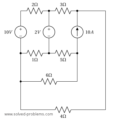
Determine the power of each source after solving the circuit by the nodal analysis.
Solution
I. Identify all nodes in the circuit.
The circuit has 6 nodes as indicated below.
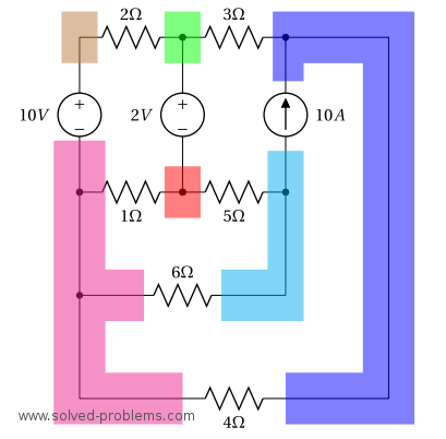
II. Select a reference node. Label it with the reference (ground) symbol.
The bottom left node is connected to 4 nodes while the other ones are connected to three or less elements. Therefore, we select it as the reference node of the circuit.
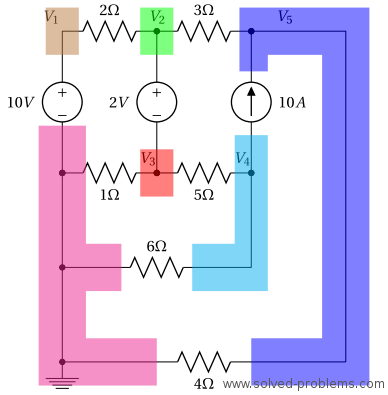
III. Assign a variable for each node whose voltage is unknown.
We label the remaining nodes as shown above. ![]() is connected to the reference node through a voltage source. Therefore, it is equal to the voltage of the voltage source:
is connected to the reference node through a voltage source. Therefore, it is equal to the voltage of the voltage source: ![]() .
.
IV. If there are dependent sources in the circuit, write down equations that express their values in terms of node voltages.
There is no dependent voltage source here.
V. Write down a KCL equation for each node.
Nodes of ![]() and
and ![]() are connected by a voltage source. Therefore, they form a supernode. The negative terminal of the voltage source is connected to
are connected by a voltage source. Therefore, they form a supernode. The negative terminal of the voltage source is connected to ![]() and the positive terminal is connected to
and the positive terminal is connected to ![]() . Thus,
. Thus, ![]() This can also be verified by a KVL around the loop which starts from the reference node, jumps to the node of
This can also be verified by a KVL around the loop which starts from the reference node, jumps to the node of ![]() with
with ![]() (the reference is always assumed to be the negative terminal of node voltages), passes through the voltage source by
(the reference is always assumed to be the negative terminal of node voltages), passes through the voltage source by ![]() and returns back to the reference node from
and returns back to the reference node from ![]() as
as ![]()
![]()
Supernode of ![]() &
& ![]() :
:
![]()
![]()
![]()
![]()
![]()
Node of ![]() :
:
![]()
![]()
![]()
Node of ![]() :
:
![]()
![]()
![]()
![]()
Hence, we have the following system of equations:

This system of equations can be solved by any preferred method such as elimination, row reduction, Cramer’s rule or other methods. We use the Cramer’s rule here:
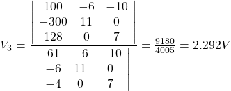
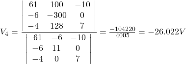
and
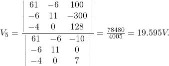
Thus,
![]()
All node voltages are found. The current of the ![]() source is the current of the
source is the current of the ![]() resistor, which is
resistor, which is ![]() The current direction shosen such that the current enters from the positive terminal of the voltage source. This is only to comply with the passive sign convention. Now that we have the source current, its power can be easily calculated:
The current direction shosen such that the current enters from the positive terminal of the voltage source. This is only to comply with the passive sign convention. Now that we have the source current, its power can be easily calculated:
![]() absorbing power
absorbing power
The current of the ![]() source equals to the summation of the currents of
source equals to the summation of the currents of ![]() and
and ![]() resistors. Therefore,
resistors. Therefore,
![]()
Consequently,
![]() supplying power.
supplying power.
The voltage across the ![]() current source is
current source is ![]() . Therefore,
. Therefore,
![]() supplying power.
supplying power.
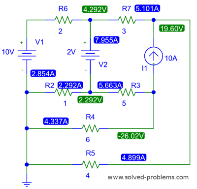
The PSpice simulation result is indicated below. The PSpice schematics can be downloaded from http://www.solved-problems.com/download/1-22.zip.

Yaz, I was searching websites about circuits and i found your website. And it’s good, thanks for sharing for other people your knowlegde.
About this problem, it’s cool to introduce to the student the differents techniques that we have for solve circuits.
I wan to add that it’s possible do a source transformation with the source of 2 v and the resistor of 2 ohms, and do too a delta-star transformation.
How can i upload by mesh analysis?
Thanks for all.
Hi,
Good that you like solved-problems.com.
It is not possible to do a source transformation with the source of 2 V and the resistor of 2 ohms because of 3 ohms resistor. If you have your solution as an image, please upload it to photobucket.com and leave the link here. Right now, my website does not have that service yet. You may also explain your solution here (in comments).
Yaz, thanks for the answer.
I was talking about the voltage source of 10 V and the resistor of 2 ohms, we could do a source transformation, that will be equivalent to have a current of 5 A, in parallel with the resistor of 2 ohms.
Can I write here using Latex? I saw that you’re using some complement of the WordPress to transform the numbers to mathematica symbol.
I’ll upload my solution in few minutes.
Well,
With no complication, I decided to work the circuit like is show on the image cause we have all the source and when we will resolving the circuits, to look for the power of every source, they will there.
I’ll resolve the problem by loop analysis, or mesh analisys like you want to call it.
Sorry for my english, it’s not good, if somebody can’t understand something, please let me know.
I show the image with the four current.
[IMG]http://i1225.photobucket.com/albums/ee383/sophiekovalevsky/Sinttulo.jpg[/IMG]
We could see that we have a supermesh.
Solving, we have:
Mesh A
-(2+1)Ia + Ic = -8
Mesh B&D (Supermesh)
-(3+5)Ib -10Id + (5+6)Ic = -2
Mesh C
-(1+5+6)Ic + 5Ib+ 6Id + Ia = 0
Auxiliar equation, if we study the node across of the current of 10 A and the 3 & 4 ohms, we know that:
I10 = Id-Ib
Doing some arrays in my equations we finaly have:
-35Ic + 15Ib +18Id = -8
-Ib + Id = 10
11Ic -8Ib -10Id = -2
Solving this lineal system equation we have our values of the currents:
Ic = 0.56 A
Ib = -5.10 A
Id = 4.90 A
Ia = 2.85 A
All these value for the currents are aproximately, with two decimal numbers.
Here, it’s the part more dificult for the student, i think that. The difference between the cases, is that with the supernode we have more easy determinate the power of every source, but in the mesh analysis is more difficult to see it. But, I think that it’s good doing by the two methods.
Power of 10V
Like we see in our image of the circuit, the convention of signs for the voltage source it’s not watch it, but we know that the power have to have the negative sign to have the convention signs. Then,
P10v = – (2.85*10) = -28.50 W
Power of 2V
We know that the current across the 2 voltage source is: Ia-Ib, and our convention signs is correct, for this reason our power is positive, we have then:
P2v = 2*(5.10+2.85) 15.90 W
Finally,
Power of 10 A source:
To calcute the power of the 10 A source we need to know the voltage between the terminals of it.
Using the VLK:
V 10A = V4 + V6
where V4 is the voltage of the resistor 4, and the V6 is the voltage in the resistor of 6 ohms.
V10 A = 4*4.90 + 6*(4.90-0.56) = 45.64 V
We know that we have to put the negative sign cuase the convention sign, and we have then:
P10A = -(10*45.64) = -456.40 W
Like we see, our answer are similar like the original problem. The different are the decimal numbers cause I olny used two decimal numbers.
Hope to help to the people and it’s my pleasure share knowledge.
Thank you very much for sharing the solution with me and my website readers. If it is ok with you, I would like to add this solution and the image as an alternative solution to the end of the post with your name.
By the way, you may use
or $latex $ for latex in comments.
Yaz, thanks.
For me, I don’t have problem to public my solution like alternative solution to this problem. But i think that we should change the image that I uploaded cause it’s horrible.
I didn’t know that i could use latex code. For the nex time.
Thanks,
Do not worry about the image.
How can i change my avatar image here?
Thanks
Please setup your avatar from http://en.gravatar.com/. solved-problems.com is able to find it by your email address used in http://en.gravatar.com/
your 6 node problem is easy to understand. THANKS for sharing
For:
“The voltage across the 10A current source is V_4-V_5=-45.617. Therefore,
P_{10 A}=10 \times (-45.617)=-456.17 W supplying power.”,
why is it not V_5-V_4 for the active sign convention?
In that case you need to use $latex P=-VI$ (See this for more info). So, again you come up with $latex P_{10 A}=-10 \times (45.617)=-456.17 W$.
thank you for this dude